Computer Networks and the Internet
This whole chapter is part of the curriculum for TTM4100.
What is the Internet?
A Nuts-and-Bolts Description
| Term | Description |
|---|---|
| host / end system | all deviced connected to a network |
| communication link | connects end systems |
| packet switch | forwards packets from an incoming comm. link to and outgoing comm. link. |
| transmission rate | number of bits transmitted per second |
| packets | a segment of data (with a given header) |
| router | type of packet switch, typically used in the network core |
| link-layer switches | type of packet switch, typically used in access networks |
| route / path | the sequence of comm. links and packet switches traversed bu a packet from the sending end system to the receiving end system |
| ISP | Internet Service Provider, end systems access the Internet through ISPs |
| protocol | control the sending and receiving of information within the Internet |
| TCP | Transmission Control Protocol |
| IP | Internet Protocol, specifies the format of the packets |
| Internet standards | developed by the Internet Engineering Task Force, documents are called RFCs |
| RFC | Request For Comments to resolve network and protocol design problems, define protocols such as TCP, IP, HTTP, SMTP |
A Services Description
We can describe the Internet as done in 1.1.1 (hardware and software components), or as an infrastructure that provides services to distributed applications.
| Term | Description |
|---|---|
| distributed application | involves multiple end systems that exchange data with each other |
| socket interface | a set of rules that specify how a program running on one end system asks the Internet infrastucture to deliver data to a specific destination program running on another end system |
The Network Edge
Access Networks
Home Access: DSL, Cable, FTTH and 5G Fixed Wireless
| Term | Description |
|---|---|
| DSL | Digital Subscriber Line, makes use of the telco's existing local telephone infrastructure |
| cable Internet access | makes use of the cable television company's existing cable television infrastructure |
| asymmetric access | has different downstream and upstream transmission rates |
| HFC | Hybrid Fiber Coax, a system where both fiber and coaxial cable are employed |
| FTTH | Fiber To The Home, provides an optical fiber path from the CO directly to the home |
| AON | Active Optical Network, essentially switched Ethernet |
| PON | Passive Optical Network |
| ONT | Optical Network Terminator |
| OLT | Optical Line Terminator |
Access in the Enterprise (and the Home): Ethernet and Wifi
| Term | Description |
|---|---|
| LAN | Local Area Network |
| Ethernet | the most prevalent (wired) access technology for LANs in corporate, universities and homes |
| WiFi | Wireless LAN access based on IEEE 802.11 technology |
Wide-Area Wireless Access: 3G and LTE 4G and 5G
Mobile devices such as iPhones and Android devices employ the same wireless infrastructure used for cellular telephony to send/receive packets through a base station that is operated by the cellular network provider. Unlike WiFi, a user need only be within a few tens of kilometers (as opposed to a few tens of meters) of the base station.
Physical Media
Examples of physical media include twisted-pair copper wire, coaxial cable, multimode fiber-optic cable, terrestrial radio spectrum, and satellite radio spectrum.
| Term | Description |
|---|---|
| guided media | the waves are guided along a solid medium |
| unguided media | the waves propagate in the atmosphere and in outer space |
Twisted-Pair Copper Wire
The least expensive and most commonly used guided transmission medium. The wires are twisted together to reduce the electrical interference from similar pairs close by. Unshielded twisted pair (UTP) is commonly used for computer networks within a building, that is, for LANs.
Coaxial Cable
Like twisted pair, coaxial cable consists of two copper conductors, but the two conductors are concentric rather than parallel. With this construction and special insulation and shielding, coaxial cable can achieve high data transmission rates. Can be used as a guided shared medium.
Fiber Optics
An optical fiber is a thin, flexible medium that conducts pulses of light, with each pulse representing a bit. Can support tremendous bit rates, are immune to electromagnetic interference, have very low signal attenuation up to 100 kilometers, and are very hard to tap. Expensive.
Terrestrial Radio Channels
Radio channels carry signals in the electromagnetic spectrum. They are an attractive medium because they require no physical wire to be installed, can penetrate walls, provide connectivity to a mobile user, and can potentially carry a signal for long distances. Prone to shadow fading (which decrease the signal strength as the signal travels over a distance and around/through obstructing objects), multipath fading (due to signal reflection off of interfering objects), and interference (due to other transmissions and electromagnetic signals).
Satellite Radio Channels
A communication satellite links two or more Earth-based microwave transmitter/receivers, known as ground stations. Two types of satellites are used
in communications: geostationary satellites (remain above the same spot on Earth) and low-earth orbiting (LEO) satellites.
1.3 The network core
Packet switching
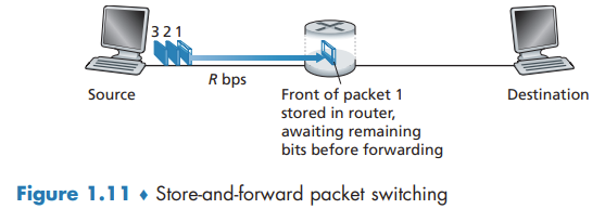
Store-and-forward Transmission
Most packet switches use store-and-forward transmission at the inputs to the links. Store-and-forward transmission means that the packet switch must receive the entire packet before it can begin to transmit the first bit of the packet onto the outbound link.
End-to-end delay
Queuing Delays and Packet Loss
For each attached link, the packet switch has an output buffer. If an arriving packet needs to be transmitted onto a link but finds the link busy with the transmission of another packet, the arriving packet must wait in the output buffer.
If the buffer is completely full, packet loss will occur - either the arriving packet or one of the already-queued packets will be dropped.
Forwarding Tables and Routing Protocols
When a source end system wants to send a packet to a destination end system, the source includes the destination’s IP address in the packet’s header. Each router has a forwarding table that maps destination addresses (or portions of the destination addresses) to that router’s outbound links. Routing protocols that are used to automatically set the forwarding tables.
Circuit Switching
In circuit-switched networks, the resources needed along a path (buffers, link transmission rate) to provide for communication between the end systems are reserved for the duration of the communication session between the end systems.
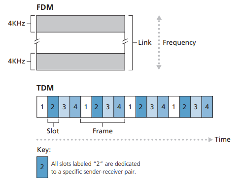
Multiplexing in Circuit-Switched Networks
A circuit in a link is implemented with either frequency-division multiplexing (FDM) or time-division multiplexing (TDM). With FDM, the frequency spectrum of a link is divided up among the connections established across the link. For a TDM link, time is divided into frames of fixed duration, and each frame is divided into a fixed number of time slots.
A Network of Networks
Our first network structure, Network Structure 1, interconnects all of the access ISPs with a single global transit ISP. The access ISP is said to be a customer and the global transit ISP is said to be a provider.
This leads to Network Structure 2, which consists of the hundreds of thousands of access ISPs and multiple global transit ISPs. A two-tier hierarchy with global transit providers residing at the top tier and access ISPs at the bottom tier.
In any given region, there may be a regional ISP to which the access ISPs in the region connect. Each regional ISP then connects to tier-1 ISPs. There is customer-provider relationship at each level of the hierarchy. We refer to this multi-tier hierarchy, which is still only a crude approximation of today’s Internet, as Network Structure 3.
To build a network that more closely resembles today’s Internet, we must add points of presence (PoPs), multi-homing, peering, and Internet exchange points (IXPs) to the hierarchical Network Structure 3. PoPs exist in all levels of the hierarchy, except for the bottom (access ISP) level. A PoP is simply a group of one or more routers (at the same location) in the provider’s network where customer ISPs can connect into the provider ISP. We refer to this ecosystem—consisting of access ISPs, regional ISPs, tier-1 ISPs, PoPs, multi-homing, peering, and IXPs—as Network Structure 4.
We now finally arrive at Network Structure 5, which describes today’s Internet. Network Structure 5 builds on top of Network Structure 4 by adding content-provider networks. Google is currently one of the leading examples of such a content-provider network.
Delay, Loss, and Throughput in Packet-Switched Networks
Overview of Delay in Packet-Switched Networks
The most important of these delays are the nodal processing delay, queuing delay, transmission delay, and propagation delay; together, these delays accumulate to give a total nodal delay.
Processing Delay
The time required to examine the packet’s header and determine where to direct the packet is part of the processing delay.
Queuing Delay
At the queue, the packet experiences a queuing delay as it waits to be transmitted onto the link.
Transmission Delay
Denote the length of the packet by L bits, and denote the transmission rate of the link from router A to router B by R bits/sec. The transmission delay is L/R. This is the amount of time required to push (that is, transmit) all of the packet’s bits into the link.
Propagation Delay
The time required to propagate from the beginning of the link to router B is the propagation delay. That is, the propagation delay is d/s, where d is the distance between router A and router B and s is the propagation speed of the link.
Nodal delay
The nodal delay is the sum of processing delay, queuing delay, transmission delay and propogation delay.
Queuing Delay and Packet Loss
Let a denote the average rate at which packets arrive at the queue (a is in units of packets/sec). The ratio , called the traffic intensity, often plays an important role in estimating the extent of the queuing delay. If La/R > 1, then the average rate at which bits arrive at the queue exceeds the rate at which the bits can be transmitted from the queue.
Packet Loss
A packet can arrive to find a full queue. With no place to store such a packet, a router will drop that packet.
End-to-End Delay
Suppose there are N - 1 routers between the source host and the destination host. The nodal delays accumulate and give an end-to-end delay
Throughput in Computer Networks
The instantaneous throughput at any instant of time is the rate (in bits/sec) at which Host B is receiving the file. If the file consists of F bits and the transfer takes T seconds for Host B to receive all F bits, then the average throughput of the file transfer is F/T bits/sec.
For this simple two-link network, the throughput is min{Rc, Rs}, that is, it is the transmission rate of the bottleneck link. The constraining factor for throughput in today’s Internet is typically the access network.
Protocol Layers and Their Service Models
Layered Architecture
Protocol Layering
To provide structure to the design of network protocols, network designers organize protocols—and the network hardware and software that implement the protocols - in layers. Each protocol belongs to one of the layers. We are again interested in the services that a layer offers to the layer above the so-called service model of a layer. Each layer provides its service by (1) performing certain actions within that layer and by (2) using the services of the layer directly below it.
When taken together, the protocols of the various layers are called the protocol stack. The Internet protocol stack consists of five layers: the physical, link, network, transport, and application layers.
Application Layer
The Internet’s application layer includes many protocols, such as the HTTP protocol (which provides for Web document request and transfer), SMTP (which provides for the transfer of e-mail messages), and FTP (which provides for the transfer of files between two end systems). We’ll refer to this packet of information at the application layer as a message.
Transport Layer
The Internet’s transport layer transports application-layer messages between application endpoints. In the Internet, there are two transport protocols, TCP and UDP, either of which can transport application-layer messages. TCP provides a connection-oriented service to its applications. This service includes guaranteed delivery of application-layer messages to the destination and flow control (that is, sender/receiver speed matching). TCP also breaks long messages into shorter segments and provides a congestion-control mechanism, so that a source throttles its transmission rate when the network is congested. The UDP protocol provides a connectionless service to its applications. This is a no-frills service that provides no reliability, no flow control, and no congestion control. In this book, we’ll refer to a transport-layer packet as a segment.
Network Layer
The Internet’s network layer is responsible for moving network-layer packets known as datagrams from one host to another. The Internet’s network layer includes the celebrated IP protocol, which defines the fields in the datagram as well as how the end systems and routers act on these fields. There is only one IP protocol, and all Internet components that have a network layer must run the IP protocol. The Internet’s network layer also contains routing protocols that determine the routes that datagrams take between sources and destination.
Link Layer
To move a packet from one node (host or router) to the next node in the route, the network layer relies on the services of the link layer. some link-layer protocols provide reliable delivery. Examples of link-layer protocols include Ethernet, WiFi, and the cable access network’s DOCSIS protocol. We’ll refer to the link-layer packets as frames.
Physical Layer
The job of the physical layer is to move the individual bits within the frame from one node to the next. The protocols in this layer are again link dependent and further depend on the actual transmission medium of the link (for example, twisted-pair copper wire, single-mode fiber optics).
Encapsulation
Note that hosts implement all five layers; this is consistent with the view that the Internet architecture puts much of its complexity at the edges of the network.
Thus, we see that at each layer, a packet has two types of fields: header fields and a payload field. The payload is typically a packet from the layer above.
Networks Under Attack
The Bad Guys Can Put Malware into Your Host Via the Internet
Our compromised host may also be enrolled in a network of thousands of similarly compromised devices, collectively known as a botnet, which the bad guys control and leverage for spam e-mail distribution or distributed denial-of-service attacks against targeted hosts.
Much of the malware out there today is self-replicating: once it infects one host, from that host it seeks entry into other hosts over the Internet.
The Bad Guys Can Attack Servers and Network Infrastructure
Another broad class of security threats are known as denial-of-service (DoS) attacks. As the name suggests, a DoS attack renders a network, host, or other piece of infrastructure unusable by legitimate users.
Most Internet DoS attacks fall into one of three categories:
- Vulnerability attack. This involves sending a few well-crafted messages to a vulnerable application or operating system running on a targeted host. If the right sequence of packets is sent to a vulnerable application or operating system, the service can stop or, worse, the host can crash.
- Bandwidth flooding. The attacker sends a deluge of packets to the targeted host - so many packets that the target’s access link becomes clogged, preventing legitimate packets from reaching the server.
- Connection flooding. The attacker establishes a large number of half-open or fully open TCP connections at the target host. The host can become so bogged down with these bogus connections that it stops accepting legitimate connections.
In a distributed DoS (DDoS) attack, the attacker controls multiple sources and has each source blast traffic at the target.
The Bad Guys Can Sniff Packets
A passive receiver that records a copy of every packet that flies by is called a packet sniffer. Some of the best defenses against packet sniffing involve cryptography.
The Bad Guys Can Masquerade as Someone You Trust
The ability to inject packets into the Internet with a false source address is known as IP spoofing. To solve this problem, we will need end-point authentication, that is, a mechanism that will allow us to determine with certainty if a message originates from where we think it does.